Experiment 8: Boost Converter under Closed Loop Voltage Control
IntroductionOutput voltage of the boost converter is compared with a reference voltage. The error is the difference between the reference and the output voltage. The feedback controller uses the error to compute the controller output, which is the duty cycle for the MOSFET in the boost converter. The feedback controller is able to regulate the boost converter’s output voltage under variation and disturbances.
- Connect the blocks for closed loop voltage control for a boost converter as shown in Figure 1.
- Enter the value of the desired output voltage ranging from 20 – 40 V in the intervals of 5 V. The controller will make the necessary measurements and set the duty cycle accordingly.
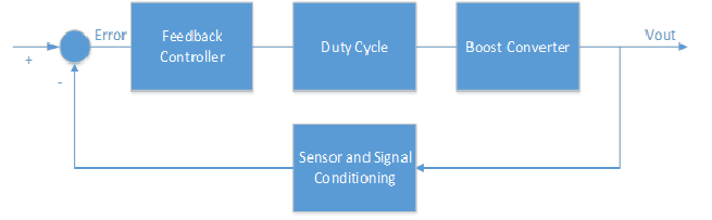
Figure 1. Feedback control System for a boost converter
- Display the output voltage waveform with different reference voltage. Pressing
 on the upper right corner of the waveform will allow you to save the image.
 - Draw a signal conditioning circuit at the output of the boost converter to reduce the voltage level by a factor of 5, and then connect to a voltage follower before sending the feedback signal to an analog to digital converter (ADC).
Contact Us
Virtual Renewable Energy Laboratory
Principal Investigator:Liping Guo, Ph.D.
815-753-1350
lguo@niu.edu
Co-Principal Investigator:
Andrew W. Otieno, Ph.D.
815-753-1754
otieno@niu.edu
The project is funded by the
National Science Foundation
Improving Undergraduate STEM Education program (DUE-1712146)
from June 2017 to May 2020.