- Home
- Experiments
- 9 - Battery
Experiment 9:
IntroductionBatteries convert electrical energy into chemical energy when charging and vice versa when discharging. Many renewable energy systems use batteries to store energy. A battery bank is a group of batteries connected in series or parallel to provide a specific voltage and capacity. Batteries supply energy to electrical loads when solar panels can not provide enough energy. Batteries also establish and stabilize system voltages and can deliver high surge currents to loads.
The most common type of battery is lead-acid batteries. Other types are Lithium-ion, nickel-cadmium, nickel-metal hydride batteries and other advanced battery technologies. Batteries are rated by their nominal voltage, charge capacity in Ampere-hours (Ah), and energy storage capacity in kW-hours (kWh).
State of Charge (SOC) of a battery is the percentage of energy remaining in a battery compared to its fully charged capacity. Charging a battery increase the state of charge, while discharging decreases the SOC. For example, a battery that is half charged is at 50% SOC.
Depth of Discharge (DOD) is the percentage of energy withdrawn from a battery compared to the fully charged capacity. For example, a battery that has had one third of its capacity discharged is at a 33% DOD. The sum of SOC and DOD should be equal to 100%.
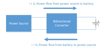
Bidirectional converters are widely used for renewable energy systems and electric vehicles (EVs). The converter interfaces between power sources and energy storage units such as battery or ultra-capacitors. It allows to flow in both directions, as shown in Figure 1. When current flows from the power source to the battery, the battery is charged. On the other hand, when current flows from the battery to the power source, the battery is discharged. The power flow in both directions reduce the size and improve efficiency and performance of the system as there is no need to use two individual converters for the forward and reverse power flow.

Figure 1. Power flow in bidirectional converters
Figure 2 shows the schematics of a buck boost type bidirectional converter. When the current reference is positive, the converter works as a buck converter, charging the battery from the power source. When the current reference is negative, the converter works as a boost converter, discharging the battery to supply power to the source.

Figure 2. Bidirectional converter
- Understand the power flow in a bidirectional converter.
- Buck boost type bidirectional converter.
- Power Source
- Capacitor
- Inductor
- MOSFETS
- Rechargable Battery
- Make connections for the block diagram of a bidirectional converter shown in Figure 1.
- Build a buck boost type bidirectional converter using the provided components: power source, capacitor, inductor, MOSFETS, and rechargeable battery.Refer to the schematics in Figure 2.
- While keeping the Voltage of the DC source at 500V, give 3 A to the current reference. Keep SOC as 50%. Determine the power flow direction. Observe the charging current to the battery.
- While keeping the Voltage of the DC source at 500V, give -5 A to the current reference. Keep SOC as 99%. Determine the power flow direction. Observe the discharging current from the battery.
- Display the schematic of the bidirectional converter that you built in the experiment.
- Display the charging current waveform for Procedure B(2). Determine the power flow direction.
- Display the discharging current waveform for Procedure B(3). Determine the power flow direction.
Contact Us
Virtual Renewable Energy Laboratory
Principal Investigator:Liping Guo, Ph.D.
815-753-1350
lguo@niu.edu
Co-Principal Investigator:
Andrew W. Otieno, Ph.D.
815-753-1754
otieno@niu.edu
The project is funded by the
National Science Foundation
Improving Undergraduate STEM Education program (DUE-1712146)
from June 2017 to May 2020.
